LensFD
Project Dataset
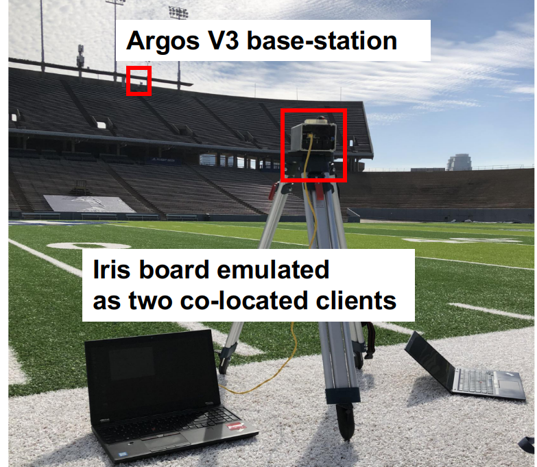
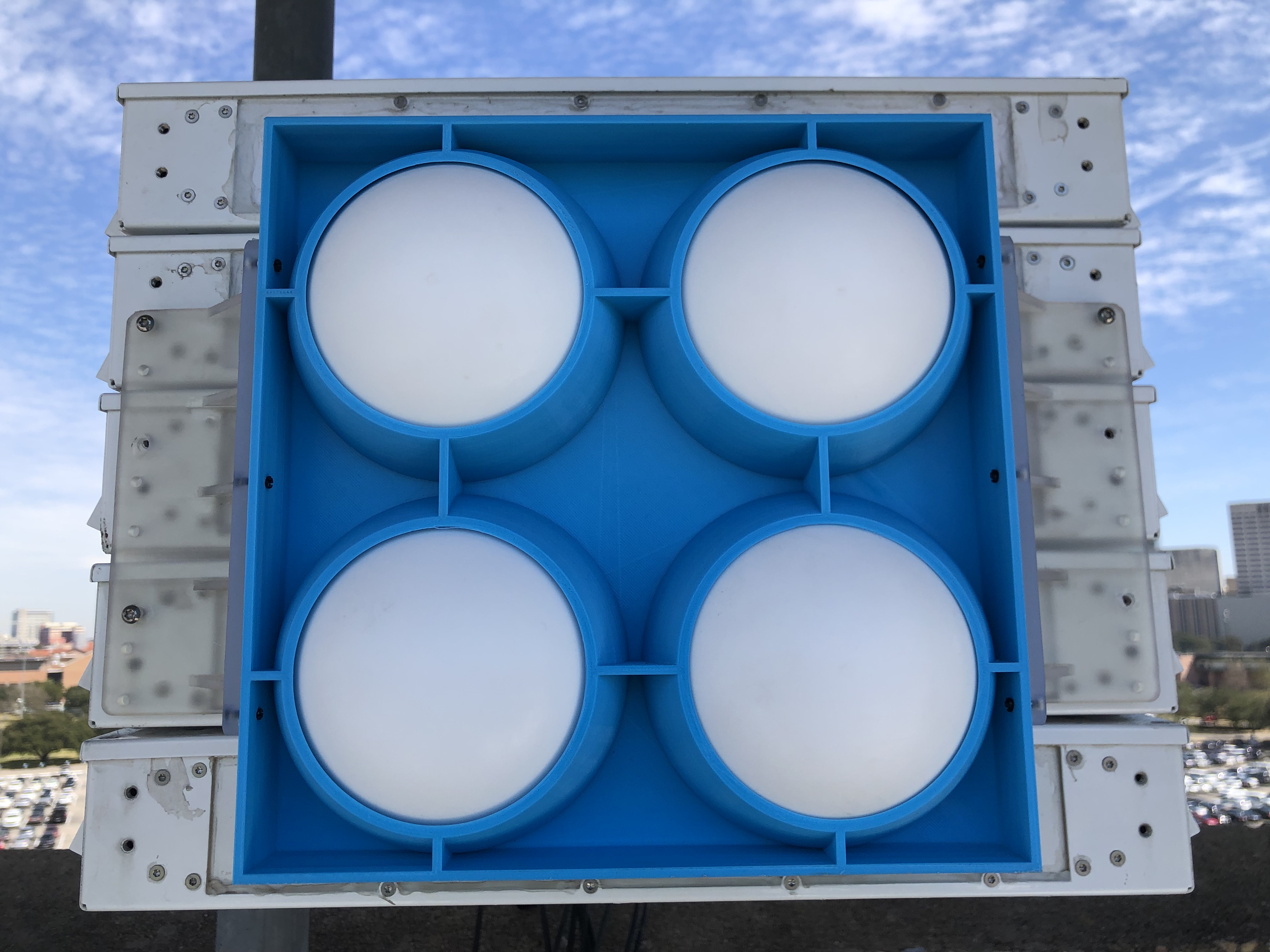
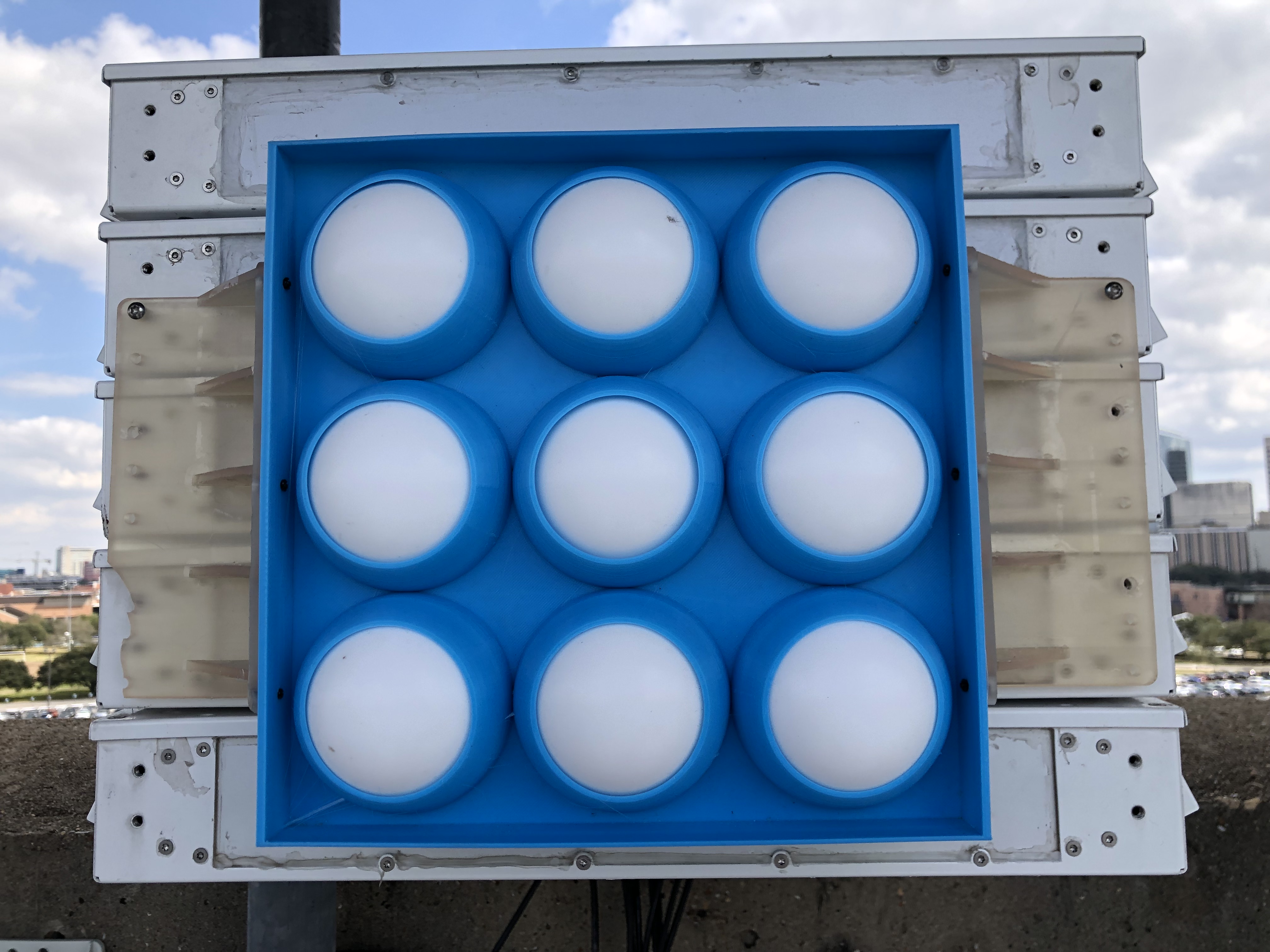
In this project, we applied 4 different lens configurations, i.e., no lens (baseline), small lens array, medium lens array, large lens array, at the massive MIMO base-stations to directly compare their performance. The massive MIMO base-station consisted of a rectangular Uniform Planar Array (UPA) with 80 3.5 GHz (CBRS band) patch antennas interfaced to 40 radios. Each radio was slant linearly polarized and thus provided two independent (±45 degree) antenna ports.
For each data, we provide both the raw IQ samples and processed Channel State Information (CSI). Note that data from both functioning radios and radios experiencing hardware failure (see description in Figure 7 of this paper) are collected and included in this dataset. More details about the base-station and client radio setup can be found in Section IV-A in this paper and Section 4.1 in this paper.
Datasets Description
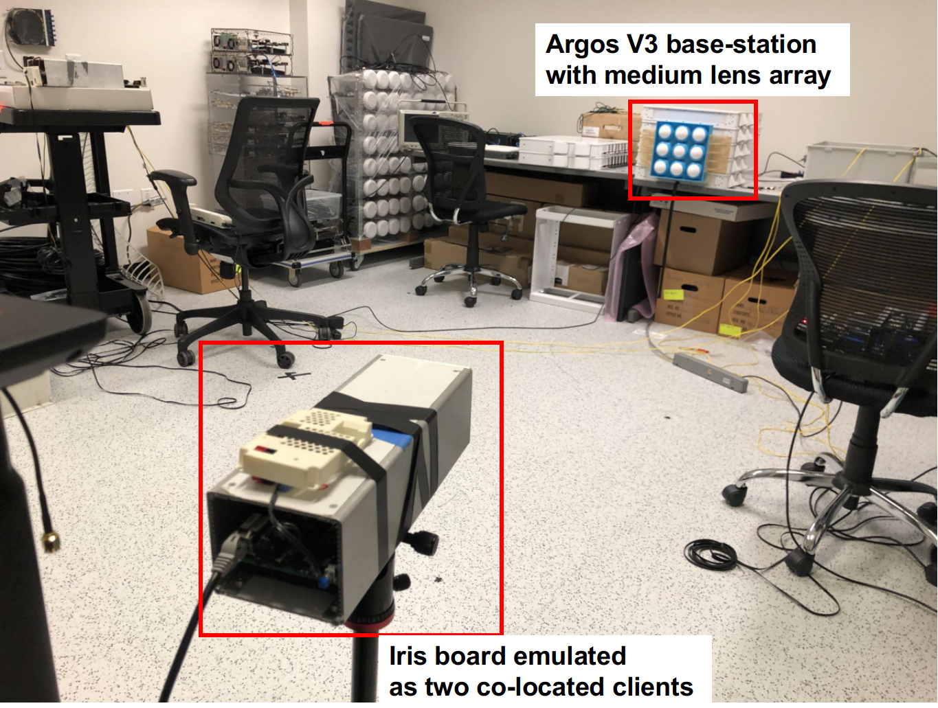
The data for project was collected in both indoor and outdoor enviroments, as shown in the pictures and maps below. For more details, see this article.
This dataset was collected by Zhican (West) Chen from Rice University, and Clayton Shepard from Skylark Wireless using the RENEW platform from both outdoor and indoor environments at Rice Univerisity campus. For any questions about this dataset, please contact the paper authors (czc0129@gmail.com) or the RENEW team.
Data Copyright and License
Rice University hereby grants you a non-exclusive, non-transferable license to use the data for commercial, educational, and/or research purposes only. You agree to not redistribute the data without written permission from Rice University.
You agree to acknowledge the source of the data in any publication or product reporting on your use of it.
We provide no warranty whatsoever on any aspect of the data, including but not limited to its correctness, completeness, and fitness. Use at your own risk.
You agree to acknowledge the following publication:
- Zhican Chen, C. Nicolas Barati, Jon Veihl, Clayton Shepard, Ashutosh Sabharwal, "LensFD: Using Lenses for Improved Sub-6 GHz Massive MIMO Full-Duplex," in IEEE Transactions on Vehicular Technology, 2023, doi: 10.1109/TVT.2023.3240558
in any publication or product reporting on your use of the data. If the data is not part of the IEEE Transactions on Vehicular Technology reference data, you also agree to acknowledge the additional source of the data, if applicable.
NOTE: Downloading, obtaining, and/or using the data in any means constitutes your agreement with these terms.
BibTeX entry:
@ARTICLE{10029875,
author={Chen, Zhican and Barati, C. Nicolas and Veihl, Jon and Shepard, Clayton and Sabharwal, Ashutosh},
journal={IEEE Transactions on Vehicular Technology},
title={LensFD: Using Lenses for Improved Sub-6 GHz Massive MIMO Full-Duplex},
year={2023},
volume={},
number={},
pages={1-13},
doi={10.1109/TVT.2023.3240558}}
Data Structure
For each lens configuration, we measured the following channels:
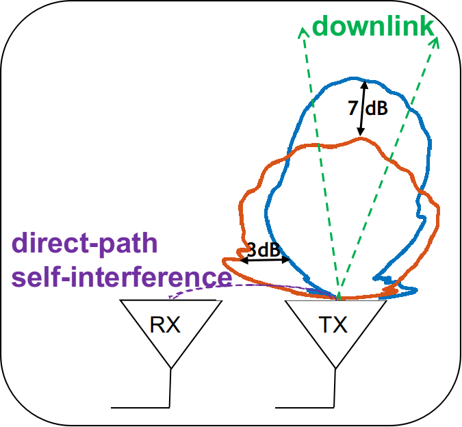
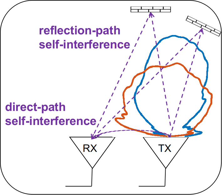
1. self-interference channel from the base-station (both indoor and outdoor)
Naming convention: (lens)-(environment)-(radio chains).(hdf5/mat)
lens: this corresponds to the lens configuration applied at the base-station. More specifically, we use "lg", "md", "sm", "no" as abbreviation for "large lens array", "medium lens array", "small lens array", and "no lens", respectively.
environment: this corresponds to the transmission environment where the data is collect. More specifically, we use "stadium" and "indoor" to refer to the outdoor environment at Rice University foot stadium and the indoor environment inside Rice Univerisity Duncan Hall, respectively.
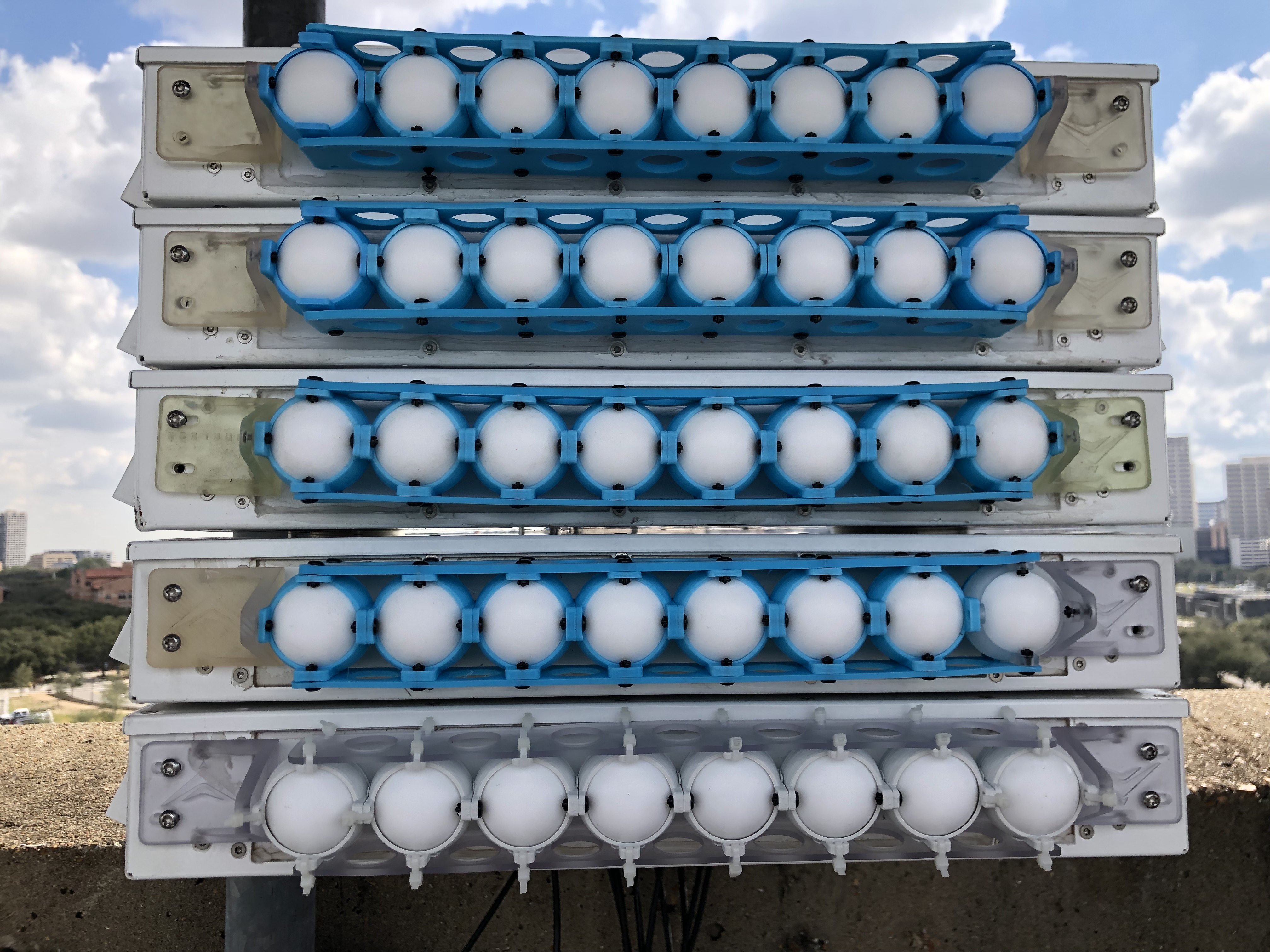
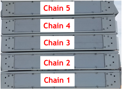
radio chains: this corresponds to the radio chains included in this data. Due to practical constraints in the backhaul throughput, it's impossible to collect and store the self-interfrence data from all 80 antennas at the base-station in one run. Alternatively, we divide the 40 base-station radios into 5 chains, and collect self-interference data from 2 chains at a time.
As shown in Figure 7 of this paper, each row of the base-station is considered a radio hub and is indexed from bottom to top. A detailed illustration can be found as the following:

hdf5/mat: raw data is in .hdf5 format, processed data is in .mat format.
For example, "lg-stadium-chain12.hdf5" is the raw self-interference data among 32 antennas from the radio chains 1 and 2, with large lens array applied at the base-station from the stadium.
2. static array-to-client (a2c) channel from 14 different user locations distributed in the scene (both indoor and outdoor)
Naming convention: (lens)-(environment)-(client location).(hdf5/mat)
lens: same as above.
environment: same as above.
client location: client location index 1-14.
hdf5/mat: same as above.
3. mobile array-to-client channel with client radio moving at human walking speed (outdoor only)
lens: same as above.
direction: this corresponds to the moving direction of the mobile node. As shown in Fig 4.2 of this paper, the mobile radio is carried by researcher and moved at walking speed. The direction "n2s", i.e., meaning "north to south" corresponds to the mobile radio moved from the left end of the red line in Fig 4.2(c) to the right end; and "s2n" corresponds to the opposite direction.
There are 5 antennas included in each data, antennas 1-2 corresponds to the dual-polarized antennas interfaced to the stationary radio; antennas 3-4 corresponds to those interfaced to the mobile client, and "antenna 5" is used for noise power measurement as no antenna is transmitting and the base-station is listenning to the noise signal.
Python API
- 1. process the raw IQ sample in hdf5 file and store it into mat file.
- 2. plot self-coupling plot from measured self-interference channels (see example as Fig.8 from this paper).
Dataset
| # | File Name | Description | Size |
|---|---|---|---|
| 1 | data_lensFD.tgz | HDF5 Dataset files | 18 GB |
| 2 | code_LensFD.zip | Processing scripts | 1 MB |